

There is no spacing that works for every solar pathway light and every path. Begin with the walking task, path shape and obstacles; place candidate lights using the selected model’s distribution information; then check the result after dark. The useful question is not “What number should I copy?” but “Where must the route remain legible, and what evidence shows that the proposed layout works?”
Why there is no universal spacing
Fixture spacing is only one input. Path width, mounting height, distribution, output mode, surface reflectance, planting and nearby light all change what reaches the walking surface. Two layouts with the same centre-to-centre distance can therefore produce different dark gaps, glare and visual guidance. A lumen value cannot be converted directly into a reliable coverage radius.
Treat spacing as the result of a layout process, not the first design input. Two candidates can start with the same nominal distance yet need different final positions because one path has a wall that reflects light and the other has dense planting that absorbs or blocks it. Record the conditions that caused each adjustment so the layout can be reviewed later.
Map the path before placing lights
Mark the path width and length, entrances, curves, junctions, steps, level changes, trees, walls and places where people pause. On a second layer, mark solar access, feasible mounting zones and maintenance routes. Keeping the lighting need separate from available mounting positions exposes compromises early.
Give every proposed light a number. That makes photographs and nighttime notes traceable: “dark patch between L3 and L4” is more useful than “the middle looks dim.”
Create two layers on the plan. The task layer marks where users must recognise an edge, turn, entrance or change in level. The constraint layer marks solar shade, planting, buried services, mowing routes and places where a fixture can actually be fixed. When a required task point and an allowable mounting point do not coincide, flag the conflict instead of hiding it with an arbitrary average spacing.
Compare layouts for straight paths
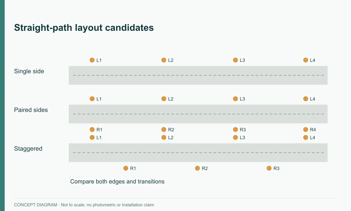
For a straight path, sketch three candidates: single-sided, paired on both sides and staggered. None is automatically best.
| Layout | Check first | Common risk to observe |
|---|---|---|
| Single side | Opposite edge and centre line | Uneven cross-path light or a weak far edge |
| Paired both sides | Sightlines and overlapping bright areas | Glare or excessive visual repetition |
| Staggered | Transitions between alternating pools of light | Dark gaps if distribution is narrower than expected |
Do not assume that doubling the number of fittings doubles useful illumination. Distribution and overlap must be evaluated on the actual surface.
Use the straight-path comparison as a test, not a style rule. Start with the arrangement that fits the ground and sightlines, then check the centreline and both edges. If a paired layout places bright sources directly in the walking view, reducing spacing alone may not solve the issue; another distribution, height or arrangement may be more appropriate.
Adjust placement at curves and junctions
At a curve, stand at the approach and look in the direction of travel. The next section of path should be understandable before a user reaches the turn. Place candidate lights around the decision point rather than dividing the curve into mathematically equal segments. Repeat the view in the opposite direction.
At junctions and entrances, identify which route, edge or destination must be recognised. Buildings and planting may block the luminous surface or solar panel even when the point looks open on a plan.
Treat steps and level changes separately
Steps require their own check because shadows can hide tread edges and an exposed source can cause glare. Review the approach, tread, edge and landing from both directions. A decorative low light does not automatically provide suitable step lighting; additional or different lighting may be necessary. Public or regulated routes require project-specific professional assessment.
Place lights near outdoor steps with a separate review
A stepped route needs more than a regular row of pathway lights. Identify the lower approach, each change of level, the upper landing and the direction people will face. Then mark where a candidate light could be positioned without occupying the walking line or creating a new obstacle. Keep handrails, doors, drainage and maintenance access visible on the plan.
Inspect tread visibility from both directions
From below, a source beyond the top landing can be directly in the line of sight. From above, a light behind the observer may create a different shadow pattern. Inspect both views rather than choosing the photograph that looks best. Record which tread or edge is difficult to recognise and whether the difficulty comes from missing light, shadow or a bright visible source.

Try changes in a controlled order: review the luminaire’s distribution and permitted mounting, compare candidate positions outside the route, then assess whether the steps need a different lighting type. Do not move a light into the tread simply to remove a shadow. If the route requires formal lighting criteria, the responsible designer should set them and determine how to verify the result. The diagram identifies review areas; it does not supply a construction detail or certify a staircase.
Example: revise a curved walkway layout
Imagine a garden path that runs straight from a gate, turns behind a shrub bed and reaches a small landing. This is a hypothetical layout exercise. The first sketch uses equally spaced markers because that is convenient on paper. The daytime review identifies a problem: one position is inside the expected mature shrub canopy, while another is next to a service access point.
Move those candidate positions on the sketch before buying fixtures. Keep the route’s task points fixed: the gate must be recognisable, the turn must be understandable on approach and the landing must be reviewed separately. Changing a light position should not quietly remove one of these tasks.
| Location | Hypothetical observation | Proposed action | What to recheck |
|---|---|---|---|
| Straight section | Opposite edge appears weak | Compare orientation or an alternative arrangement | Both edges and source visibility |
| Before the bend | Next section disappears behind planting | Compare a position that reveals the turn | View approaching and leaving the bend |
| Inside the bend | Mature shrub would cover the panel | Move the candidate within a suitable mounting zone | Daytime solar access and nighttime target |
| Landing | An edge is hidden by shadow | Review step-specific lighting | Tread, edge and both approaches |
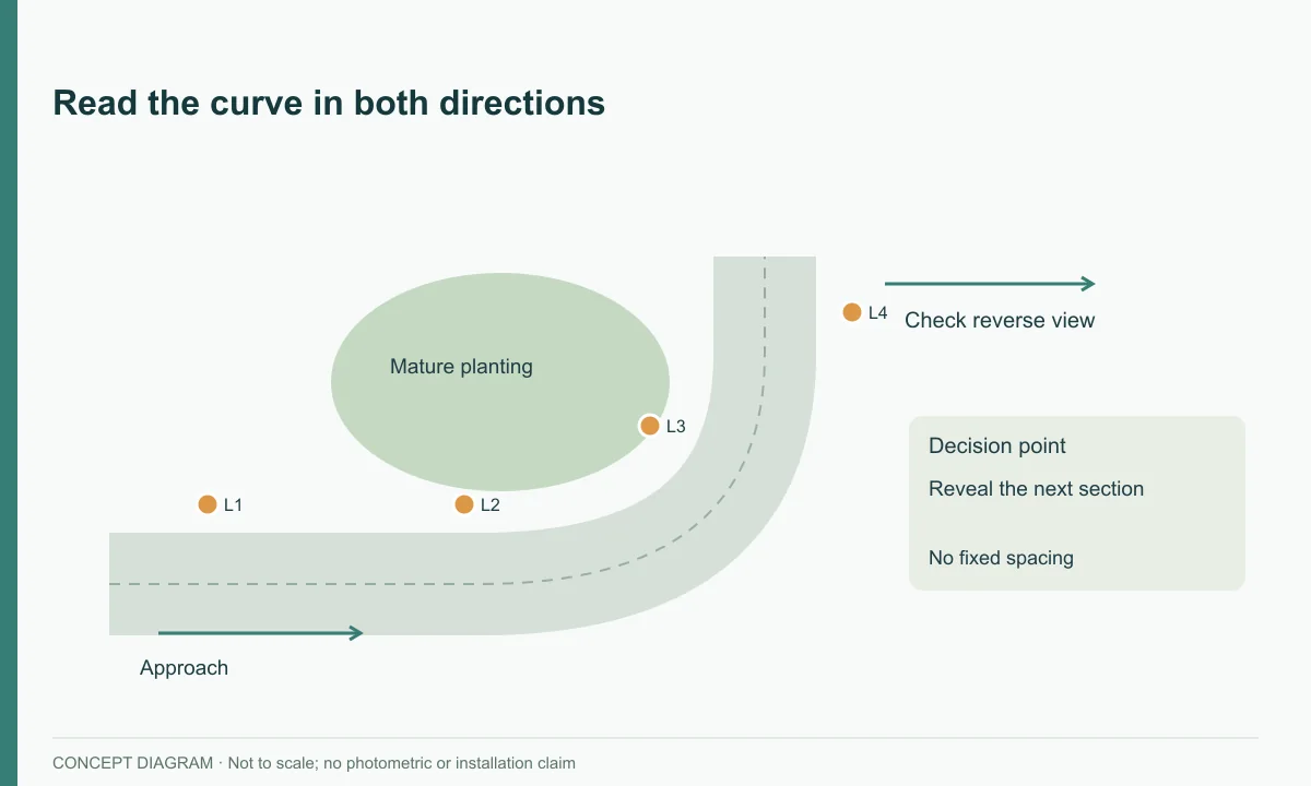
The changes are responses to observed constraints, not universal placement instructions. The final number of lights cannot be derived from this sketch because it contains no product distribution, measured dimensions or verified lighting criteria. For real work, attach those inputs to the same location IDs.
Trial the layout and refine it after dark
Temporarily mark or place fittings only where it is safe and permitted. Record the model, mode, weather, recent charging conditions and observation time. Walk the route in both directions, checking dark gaps, glare, blocked light and confusing transitions. Move one variable at a time, then repeat the check.
| Light IDs / area | Initial observation | Change made | Recheck result | Conditions recorded? |
|---|---|---|---|---|
| ______ | ______ | ______ | ______ | Model / mode / time / weather |
| ______ | ______ | ______ | ______ | Model / mode / time / weather |
A photograph helps document visible issues, but exposure and image processing can make a scene look brighter or darker. If a project requires illuminance or uniformity measurements, record the instrument, grid, height, time, operating mode and original readings.
A repeatable placement workflow
- Mark the route, decision points and level changes on a dimensioned plan.
- Add solar access, physical mounting zones and maintenance constraints.
- Select one candidate fixture and obtain its applicable optical and operating-mode information.
- Number an initial set of positions; do not treat their first spacing as final.
- Observe the route after dark from both directions and note one problem per location ID.
- Change one variable at a time, then repeat the observation under recorded conditions.
This workflow produces a site-specific answer without pretending that one distance fits every path. It also separates a visual trial from a formal measurement exercise: both can be useful, but they support different claims.
Use a nighttime check that helps the next decision
Prepare the observation route before dark. Choose repeatable places to stand, keep the same travel direction for each pass and note whether nearby building lights are operating. If those lights are later switched off, repeat the check; they may have been contributing to the apparent result.
A useful note names the problem and a possible next test. “L3 to L4: the outer edge disappears when approaching from the gate; compare the next candidate position” is actionable. “Needs more light” leaves the supplier unsure whether to change distribution, output, position or quantity. A complete record also states when the observation was made relative to the light’s operating program.
Compare visible contexts in the garden-light application gallery when discussing route shape. If the layout involves a higher mounting position, review post-top courtyard fixture forms separately from low-level products. Neither page supplies a universal spacing value; the selected fixture and actual route remain the basis of the check.
Frequently asked questions
Can brighter lights always be spaced farther apart?
No. Output must be considered with distribution, mounting position, path width and the target surface.
Must pathway lights be staggered?
No. Staggering is one candidate arrangement. Compare it with single-sided and paired layouts under the actual site conditions.
Is a nighttime photograph enough to validate spacing?
It is useful for documenting visible problems, but it is not a substitute for a defined measurement method when quantitative performance is required.
Use the solar pathway light and solar bollard light ranges to identify the fixture form, and the yard-light selection guide for the wider decision. Send a dimensioned path plan, curve and step photos, and the candidate model before requesting a layout review.