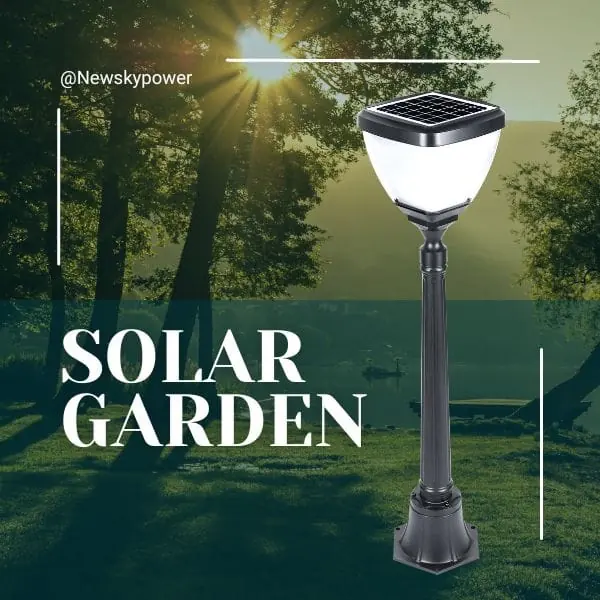


Choose a solar pillar light by matching the usable mounting surface, the light’s base and its fixing layout. The width of the lamp body is only one part of the fit. A light can look proportionate on a gate pillar yet fail to sit properly on its cap, or have fixing holes that do not suit the available structure.
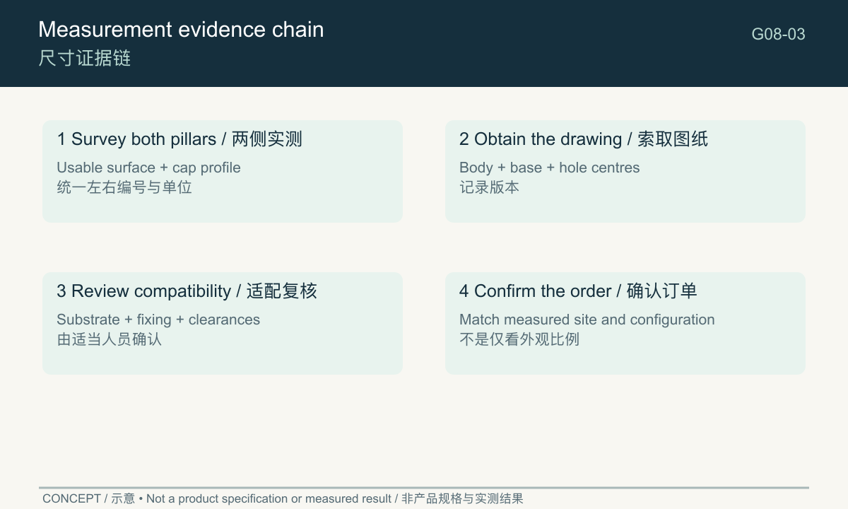
Measure the existing pillar, obtain the dimensioned drawing for the exact light and compare the two before ordering or drilling. Nominal descriptions such as 4×4 or 6×6 are not substitutes for actual dimensions and a compatible mounting method.
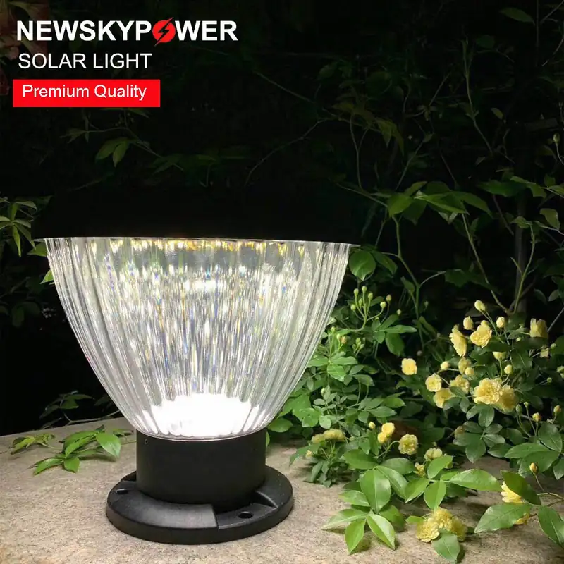
Pillar Lights vs Pole Lights
A pillar light sits on or attaches to an existing raised support, such as a gate pillar or boundary-wall pier. A pole light uses a pole assembly as part of its installation. Both may occupy an entrance, but their mounting questions are different.
Start with the support you actually have
For an existing pillar, record the material, cap shape, usable top surface and condition. Also note whether the cap is a separate decorative element or part of the structure intended to receive fixings. A visually substantial cap should not automatically be treated as a suitable anchoring substrate.
For a new entrance, coordinate the pillar and lighting drawings before the cap is fabricated. This creates an opportunity to align appearance and mounting requirements, while still leaving the structural details to the relevant designer or installer.
The solar pillar light category helps distinguish these forms from freestanding pole assemblies. Use the category to shortlist a style, then request product-specific dimensions.
Keep scale and fit as separate decisions
A broad housing may look balanced on a wide pier, but that does not prove the base fits. A compact housing may fit mechanically yet look lost against a large gate. Evaluate both questions rather than assuming that a pleasing photograph resolves installation.
Photograph the entrance straight on and from its normal approach. Include the gate, adjoining wall and any existing fixtures. These views help judge scale; the measurements and drawings will answer fit.
Measure the Usable Pillar Surface
Do not start with the largest outside dimension
The overall cap width may include a sloping edge, bevel or decorative overhang. The usable mounting surface is the area that can support the base and its approved fixing arrangement. Measure that area separately in both directions.
Record any crown, slope, unevenness or existing hole. A flat-looking photograph can conceal a top surface that does not provide the contact required by the light’s base. Do not assume tightening the fixings will safely pull the base into contact.
A simple survey avoids ambiguous quotations
Make a plan sketch with an orientation mark facing the gate. Write measured width and depth, the usable surface boundary and the position of obstructions. Add a side view if the cap is sloped or raised.
For a pair of gate pillars, measure both. Existing structures that look symmetrical can have different cap dimensions or surface conditions. Label them left and right as viewed from a defined approach, so photographs and measurements remain consistent.
Record uncertainty as well. If part of the cap cannot be measured safely, mark it as unmeasured and arrange suitable access. A guessed dimension is harder to detect once it has been copied into an order.
The SML-002 pillar-light page is a relevant product reference; request the exact current base drawing rather than scaling dimensions from its image.
Check Body, Base and Mounting-Hole Dimensions
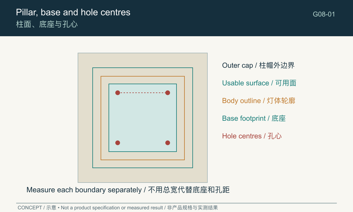
The body outline, base footprint and hole centres answer different questions. The body affects appearance and overhang. The base identifies the contact footprint. The hole pattern defines where the approved fixings must pass into a suitable support.
Compare all three layers
Record the hole spacing as centre-to-centre dimensions, not as the distance between the outside edges of two holes. Keep the drawing’s measurement convention with your survey.
Ask for overall body width and depth, base dimensions and the centre-to-centre fixing distances. The drawing should also identify the mounting orientation and any relevant access space. A single overall dimension cannot replace this information.
For a hypothetical pillar, imagine a 220 mm square cap with a 180 mm square flat central area. A hypothetical 160 mm square base fits inside that flat outline geometrically. That does not establish an approved installation: hole position, substrate, edge distances and mounting instructions still need checking.
These numbers illustrate the method only. They are not dimensions of the photographed product or recommended clearances. The example’s useful conclusion is “base outline fits the measured flat area”, not “installation approved”.
What about 4×4 and 6×6 posts?
A light advertised for a nominal post category is not automatically compatible with every post carrying that name. Measure the actual support and identify whether the light uses an over-post cap, a flat base or an adapter.
Confirm the exact compatible dimension range and mounting arrangement with the supplier. Do not force a cap onto a post, alter a base or assume a similar adapter is suitable. Matching labels without matching the geometry and fixing method can leave the real installation unresolved.
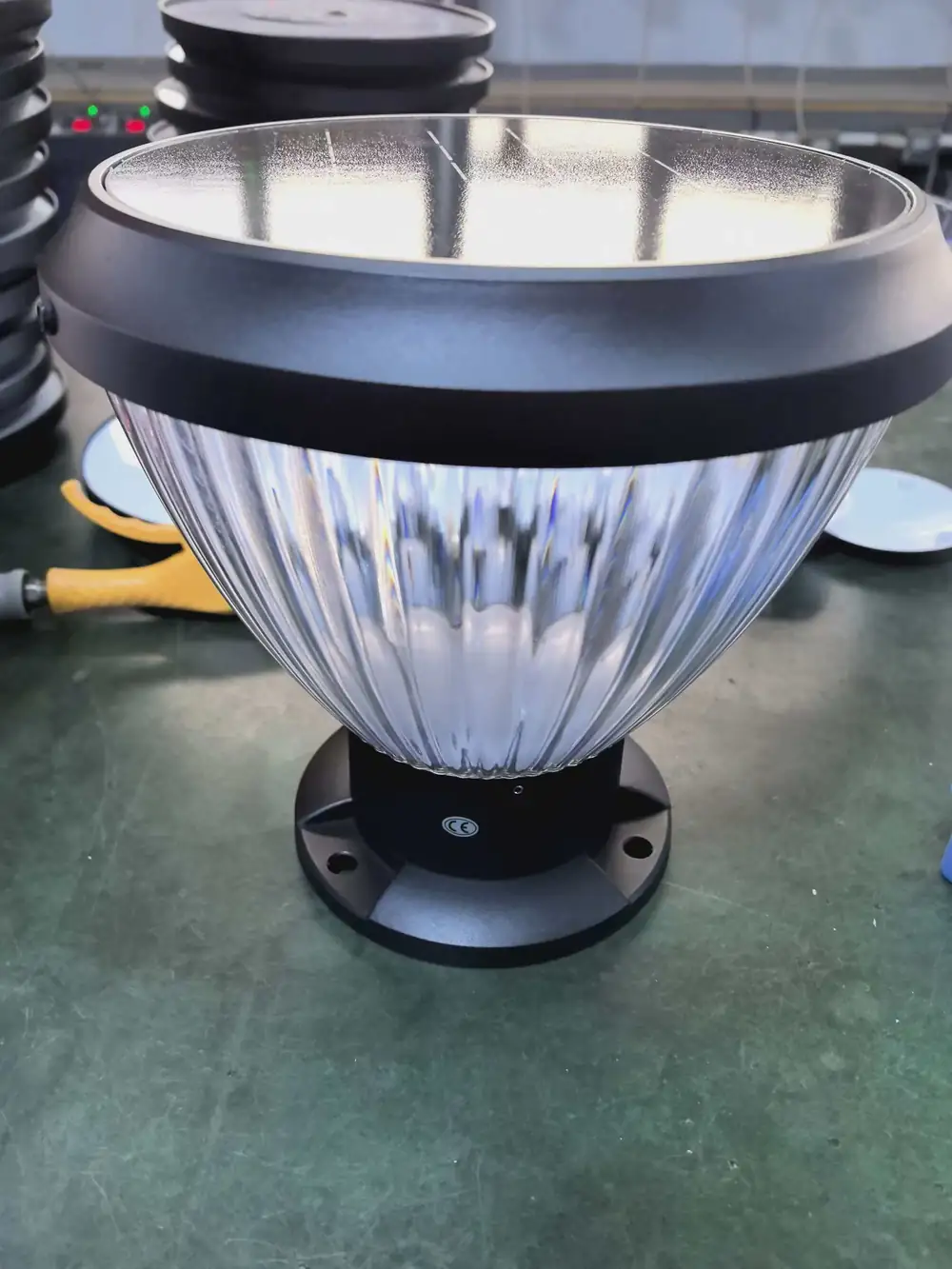
Inspect Cap Surfaces and Obstructions
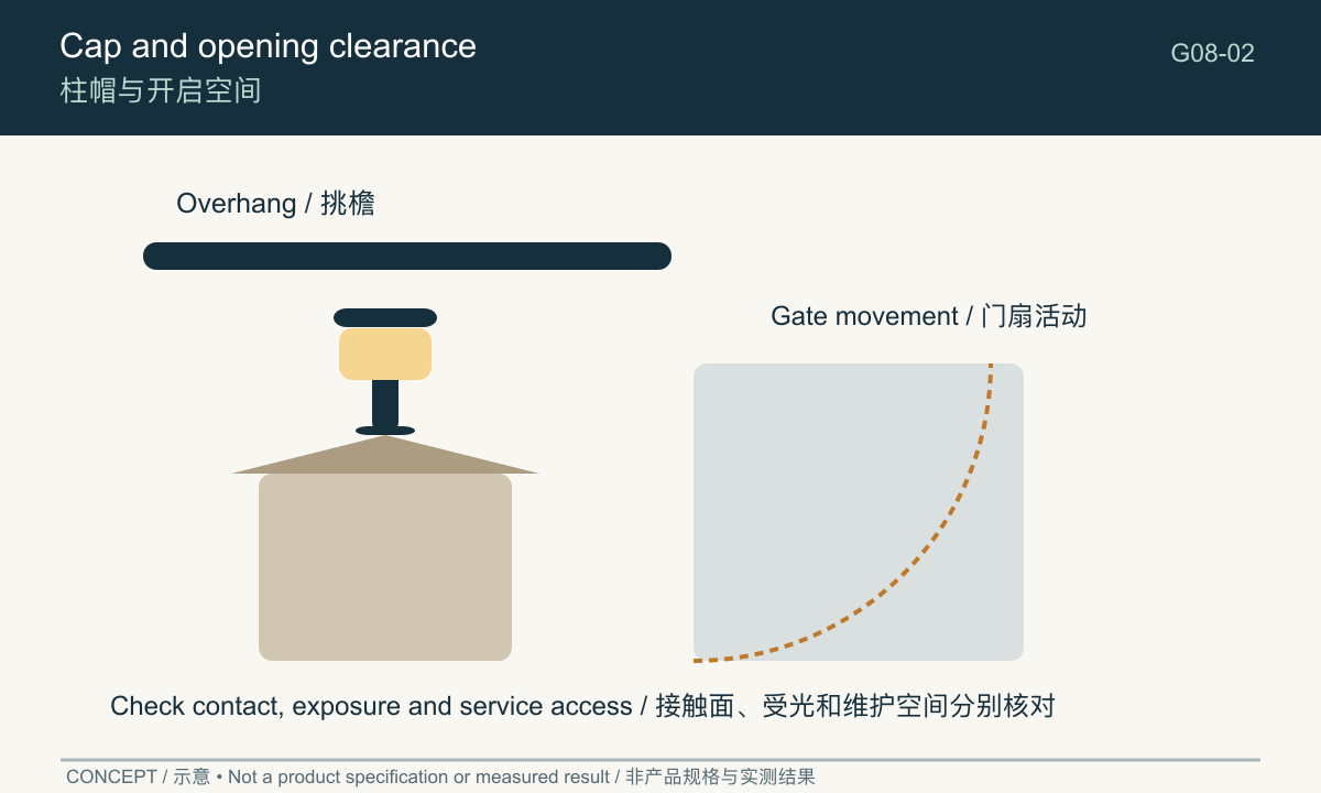
A correct plan footprint is only part of the check. Look above, around and beside the mounting point. Gate leaves, hinges, decorative finials, climbing plants and nearby walls may interfere with the housing or its service access.
Review movement and access
Open the gate through its normal travel and inspect the space around the proposed fixture without placing an unsecured light in the moving path. Check whether service procedures require access from above or a particular side, using the exact product instructions.
Consider how the solar collecting surface will remain exposed. A cap under an overhang can accommodate the base perfectly yet be a poor solar location. Nearby foliage may create a similar conflict as it grows.
Assess the condition before choosing fixings
Cracks, loose caps, deterioration or uncertain construction require assessment before installation. The installer should identify the suitable fixing method for the substrate and product instructions. This article does not specify a universal screw, drilling depth or anchor arrangement.
Keep water pathways in mind without improvising a sealing solution. The required contact, drainage and sealing details belong to the model’s mounting instructions. Adding sealant wherever a gap appears can conceal a poor fit or interfere with the intended arrangement.
Finally, check the visible result from both sides of the entrance. A centred body may not mean a centred base, and an offset base may have a defined orientation. Resolve those details on the drawing before making irreversible holes.
Confirm Fit with a Dimensioned Drawing
Use a measurement checklist that distinguishes evidence
| Item | Site record | Product evidence | Decision |
|---|---|---|---|
| Pillar outline | Actual width and depth | Body outline | Judge visual proportion |
| Usable top | Flat or otherwise approved contact area | Base footprint | Check geometric accommodation |
| Hole layout | Existing holes and substrate boundaries | Hole-centre drawing | Installer to confirm fixing compatibility |
| Cap profile | Slope, crown, bevel and level changes | Mounting-surface requirements | Resolve contact before installation |
| Movement | Gate travel and nearby objects | Housing and service envelope | Confirm no interference |
| Solar exposure | Overhangs and present or future foliage | Panel location | Review the proposed position |
| Identity | Left/right pillar labels and photographs | Model and drawing revision | Keep survey and order aligned |
Attach the measurements to the actual drawing revision. If the supplier changes the base or offers an adapter, repeat the affected comparison. A verbal assurance that “this size usually fits” is weaker than a drawing linked to your measured surface.
Confirm a pair before placing a batch order
Keep the measurement units visible on every sketch. If the site survey uses millimetres and a supplier describes a nominal post size in inches, convert the stated dimensions explicitly while retaining the original values. A unit conversion can resolve arithmetic, but it cannot resolve an undefined nominal size. Request the actual compatible dimensions before treating the two descriptions as equivalent.
For two gate pillars, review both sides independently, then compare the pair visually. If their usable surfaces differ, the solution may require a supported mounting option or a revised product choice rather than simply centring identical housings.
Where useful, use a safe non-installed mock-up to assess scale. Keep it separate from structural approval and a lit sample review. A cardboard outline can reveal an awkward overhang, but it cannot confirm anchoring strength or night-time appearance.
For the wider entrance composition, use the yard lighting selection guide to consider adjoining wall and path fixtures. Do not let a matching decorative style override the mounting checks.
Send the supplier a labelled plan, side-view photographs and the measured usable surface. Ask for a dimensioned drawing showing the body, base and fixing centres of the proposed configuration. That is the practical next step in choosing solar pillar light size: establish what fits, how it is supported and what evidence supports the decision.
Frequently asked questions
What base size fits a pillar light?
The base must match the usable support and approved fixing arrangement. There is no universal base-to-pillar ratio that establishes compatibility.
Can I use existing mounting holes?
Only after the hole pattern, substrate condition and product requirements have been checked. Similar spacing alone is not enough.
Should the lamp be smaller than the pillar cap?
Compare the actual body and base separately. A visual preference for overhang or inset does not establish safe support or fixing compatibility.
For an overview of fixture types, site conditions and selection priorities, see our garden and courtyard lighting guide.