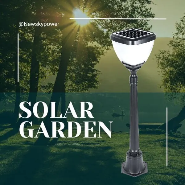


Choosing solar courtyard light mounting height starts with the lighting task, the fixture and the pole—not a universal height recommendation. A light that slides onto a pole has passed only one part of the fit check. Its connection, supporting structure, solar access and light distribution still need separate confirmation.
For an existing pole, collect evidence before selecting a replacement head. For a new installation, define the reference points before comparing dimensions. In both cases, the useful outcome is a coordinated information set that the supplier, lighting designer and installation team can review without guessing what a measurement means.
This guide concerns preparation and verification for garden and courtyard applications. It does not provide a pole, foundation or electrical design. The same information structure can serve island projects, Southeast Asian developments, Australian communities and European or North American sites, while the actual environmental and project requirements remain local.
Identify the Fixture and Mounting Type
Separate the head from the complete assembly
Start by identifying what is being purchased. A courtyard luminaire supplied as a head is different from an assembly including a pole, arms and mounting accessories. The presence of those parts in a catalogue photograph does not establish that they are included in the quotation. Ask for a component schedule with a configuration reference that also appears on the drawing.
The solar courtyard lights range provides a starting point for reviewing head forms. When the requirement includes a coordinated pole assembly, compare the scope of solar pole lights separately. Neither category name is a substitute for a model-specific supply list.
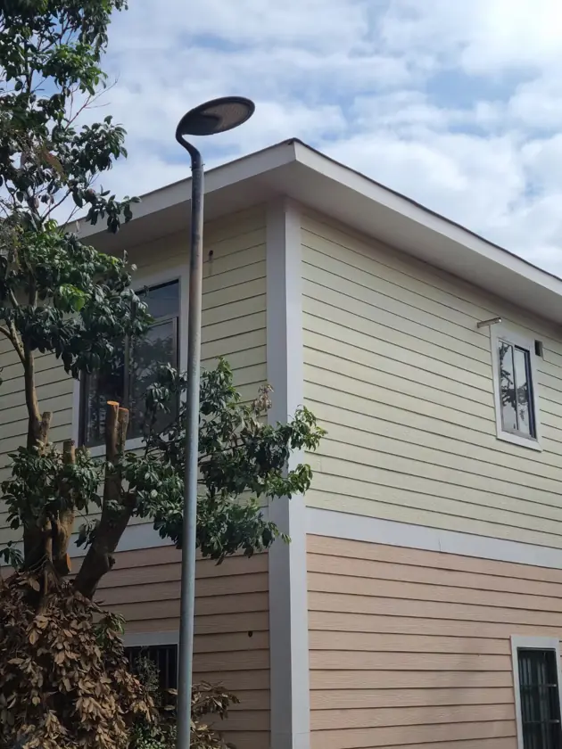
Solar post top lights describe a mounting form, not a universal interface. The published SCL-008 application can help identify a post-top product context, but another site’s photograph cannot confirm solar light mounting compatibility for the pole being assessed.
Name the actual connection
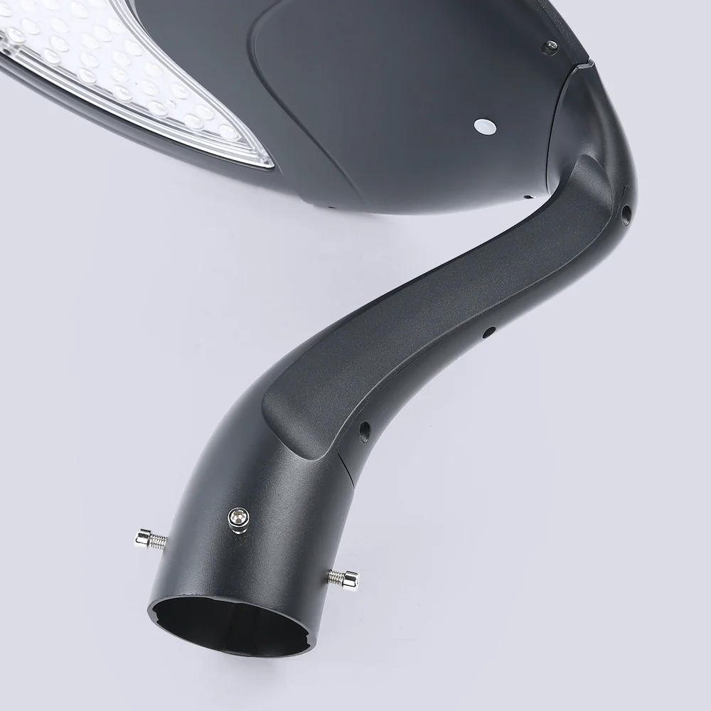
Identify the two mating parts: the fixture socket and pole top, or the bracket and its supporting surface. Use the manufacturer’s connection terminology. If an arm is involved, record its orientation and the complete configuration rather than treating the head as if it sits directly on a vertical pole.
Request a general assembly drawing and a detail of the interface. A photograph can help someone locate the relevant component, but it cannot establish hidden contact surfaces, tolerances or the permitted fixing arrangement. If the connection type is unknown, leave it unresolved in the inquiry rather than choosing an adapter by appearance.
What Mounting Height Changes
Establish the measurement reference
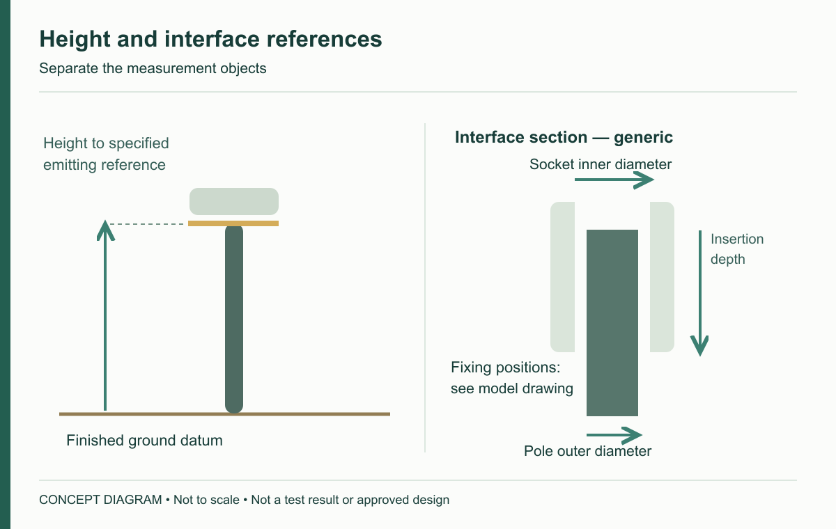
Write down where height begins and ends. Finished ground level, top of foundation, pole length, socket level and the emitting surface are different reference points. A pole described by its overall length may not place the light at that same height after installation. Sloping ground makes a photograph with an unlabelled arrow particularly ambiguous.
Record the reference at each proposed position. Include the relevant target surface, such as a pedestrian path, entrance threshold or seating area. When two suppliers use different definitions, ask each to restate the height against the same project datum before comparing their proposals.
Evaluate light, surroundings and support together
Height changes the relationship between the light source, the task and nearby observers. Review path width, changes in level, mature planting, windows and the visibility of the emitting surface. A manufacturer’s suggested height can help identify a candidate, but it does not establish a suitable layout for every site.
Keep the lighting assessment distinct from the structural review. Changing height or adding an arm changes the assembly being evaluated. Ask the responsible designer what supporting information is required; do not infer an acceptable configuration from a similar installation photo. A brighter fixture also does not automatically resolve an unsuitable mounting position.
Solar access adds another check. A higher position might clear one obstruction while remaining shaded by a building or larger tree. Review the panel’s actual position and the site’s relevant seasons. The Department of Energy’s solar radiation overview explains why location, season and atmospheric conditions matter; daylight duration alone is not a charging-performance result.
Pole Diameter, Insertion Depth and Fixings
Measure the object, not just a number
When asking what pole diameter fits a solar post top light, identify whether a dimension describes the pole’s outer diameter or the fixture socket’s inner diameter. Those measurements have different purposes and should not be copied interchangeably into an order. The drawing must also state units, tolerances and the revision used for the comparison.
Insertion depth is the effective engagement length allowed by the design, not simply the depth of an accessible opening. Internal stops, taper, surface finishes and other features may affect the relationship. Obtain the manufacturer’s detail instead of estimating usable engagement from a photograph of the underside.
Record fixing positions without inventing instructions
Mark where fixings act and which parts they secure. Request the appropriate fastener and installation information for the actual version. Do not create a universal screw count, tightening torque or hole pattern from another model’s manual. A difference between two documents is a clarification item, not an invitation to combine them.
Use the following measurement worksheet as a request format. The empty result fields are deliberate: this is an information checklist, not a dimensional approval.
| Interface item | Record from site | Obtain from supplier | Confirmation needed |
|---|---|---|---|
| Pole top | Measured object, condition and units | Permitted supporting geometry | Corresponding drawing reference |
| Fixture socket | Candidate identity | Inner diameter and tolerance | Same configuration and revision |
| Engagement | Accessible arrangement, if safely documented | Required insertion depth and stops | Effective mating length |
| Fixings | Existing features, without alteration | Approved positions and hardware | Compatible connection method |
| Orientation | Proposed head or arm direction | Allowed assembly orientation | Lighting and structural review |
Check Adapters and Existing Poles
Treat reuse as a proposal
An existing pole may look serviceable while its history, foundation or previous modifications remain unknown. Gather available drawings, inspection records and photographs taken from safe positions. Identify who is responsible for assessing the pole, its connection and its foundation. An interface match cannot answer all three questions.
On an island project, retaining a sound pole may be commercially attractive because of transport and handling constraints. That is a reason to investigate reuse, not proof that reuse is acceptable. Compare the information and work needed for retention with the alternative of a new coordinated assembly before making the order depend on an unverified assumption.
Ask what the adapter is approved to do
An adapter changes the connection arrangement. Confirm the exact fixture, supporting pole, adapter version and allowed assembly with the relevant supplier and project reviewer. Include any changed offset, orientation or overall arrangement in the information submitted for assessment.
Do not solve a mismatch by recommending grinding, drilling, packing or improvised sleeves. If a permitted adapter cannot be documented, keep that candidate on hold and request another supported configuration. “Universal fit” is not an adequate answer to a model-specific compatibility inquiry.
Describe exposure rather than assuming a regional rating
State whether a particular site has coastal exposure, seasonal cold, heavy planting or difficult maintenance access. These conditions do not apply equally to every island, Australian region or European location. Ask for evidence relevant to the connection and complete assembly; a housing material name alone does not establish suitability for that exposure.
Prepare Dimensions Before Ordering
Build one coordinated inquiry
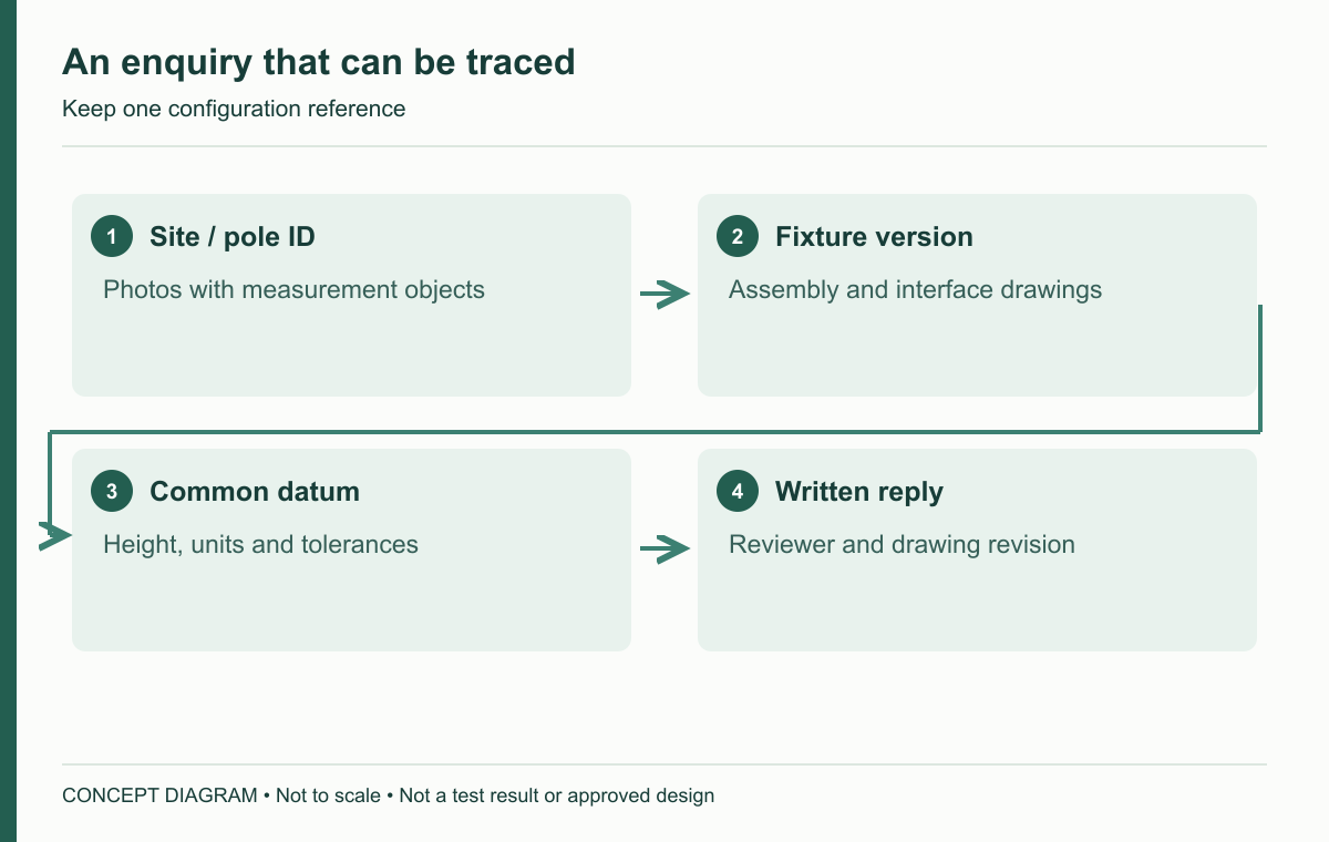
Use a shared position identifier on the site plan, measurement photos and worksheet. Include the candidate model, intended height datum and current drawing revision. A photo should show what was measured and where, without requiring anyone to climb a pole simply to complete a purchasing form.
| Position ID | Field to complete | Evidence to attach | Responsible confirmation |
|---|---|---|---|
| To assign | Existing or new pole information | Available drawing and safe photographs | Asset owner or structural reviewer |
| Same ID | Candidate head and accessories | Supplier configuration schedule | Supplier |
| Same ID | Mating dimensions and references | Dimensioned interface detail | Supplier and installation team |
| Same ID | Proposed mounting height | Datum-marked site section | Lighting and structural reviewers |
| Same ID | Lighting task and surrounding constraints | Path, window and planting plan | Project team |
| Same ID | Accepted document set | Revision and written response | Named project approver |
Give unanswered questions an owner and a next action. For example, a missing socket tolerance belongs in the supplier inquiry; an undocumented foundation belongs with the responsible site reviewer. Keeping those requests separate prevents a supplier’s dimensional reply from being mistaken for complete structural acceptance.
Keep delivery and site documents aligned
For a remote or multi-stage project, record which parts must arrive together and how their identities will be checked. Separate cartons may contain related components, but carton proximity is not proof of compatibility. Put the configuration reference on the packing and receiving records where appropriate.
If a drawing changes after quotation, compare the affected dimensions, accessories and responsibilities before accepting the revision. Record what has changed and who accepted it. A forwarded photograph with “same as before” is difficult to reconcile later when the installed assembly and purchasing record differ.
Trial Fit and Final Checks
Use three separate acceptance questions
A controlled trial fit, performed under the manufacturer’s instructions and the project’s procedures, can reveal whether delivered parts correspond to the documented geometry. It does not by itself establish structural suitability or the nighttime lighting result. High-level work and structural confirmation belong with appropriately qualified personnel.
Keep the record divided into geometry, connection/support and lighting. For each, list the required evidence, result and reviewer. “Fits,” “lights up” and “accepted for the intended position” are different statements. Preserve photographs and the exact product revision so that a later replacement can be assessed against a known assembly.

Review a hypothetical retrofit decision
Consider a courtyard with a documented path layout but incomplete records for its existing poles. The first candidate has a visually similar socket. The second is offered with a documented connection arrangement but requires a different support. Neither should win solely on the apparent convenience of the first photograph.
The practical next step is to obtain the missing interface and support information, then compare the two complete options. Retention may avoid some replacement work if the relevant reviews support it. A new assembly may provide a clearer documentation path, but still requires site-specific approval. The worksheet makes those trade-offs visible without pretending that either outcome has already passed.
Frequently asked questions
Is a similar pole diameter enough to confirm fit? No. Confirm the measured object, tolerances, effective engagement, fixing arrangement and supporting structure. Similar dimensions can identify a candidate; they do not complete the approval.
Is a higher mounting position always better? No. It changes the relationship with target surfaces, observers, planting and the support. Compare a documented lighting proposal and structural configuration rather than deriving coverage from height alone.
Can I use a universal pole adapter? Only a specifically supported arrangement should proceed for review. Ask for compatibility information covering the exact fixture, pole and adapter; do not rely on the word universal or an improvised fit.
To begin a model-specific discussion, send the supplier your mounting information: position IDs, safely obtained photos, measurement references, proposed height and the candidate configuration. A clear inquiry is more useful than a single diameter without context.
For an overview of fixture types, site conditions and selection priorities, see our garden and courtyard lighting guide.