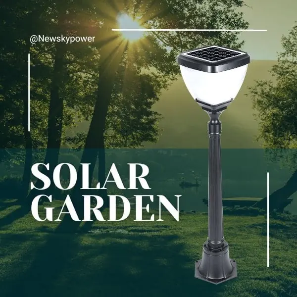


Install a solar flood light with a separate panel by planning three things together: where the light must illuminate, where the panel can receive useful sunlight, and how an approved cable can connect them. Choose height and aiming from the lighting task and product guidance, then verify the result at night. There is no single mounting height or cable extension limit that applies to every model.
The most useful installation plan starts before drilling. Mark the proposed lamp and panel positions, trace the real cable route, identify suitable mounting surfaces, and confirm access for future maintenance. This avoids discovering that a well-placed lamp cannot reach a suitable panel location after the brackets are already fixed.
Gather the Product Instructions and Site Information First
Check Accessories, Connectors, Brackets, Instructions, and Mounting Surfaces
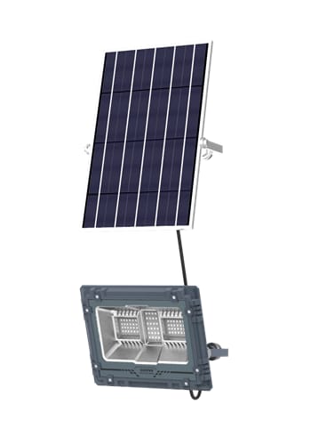
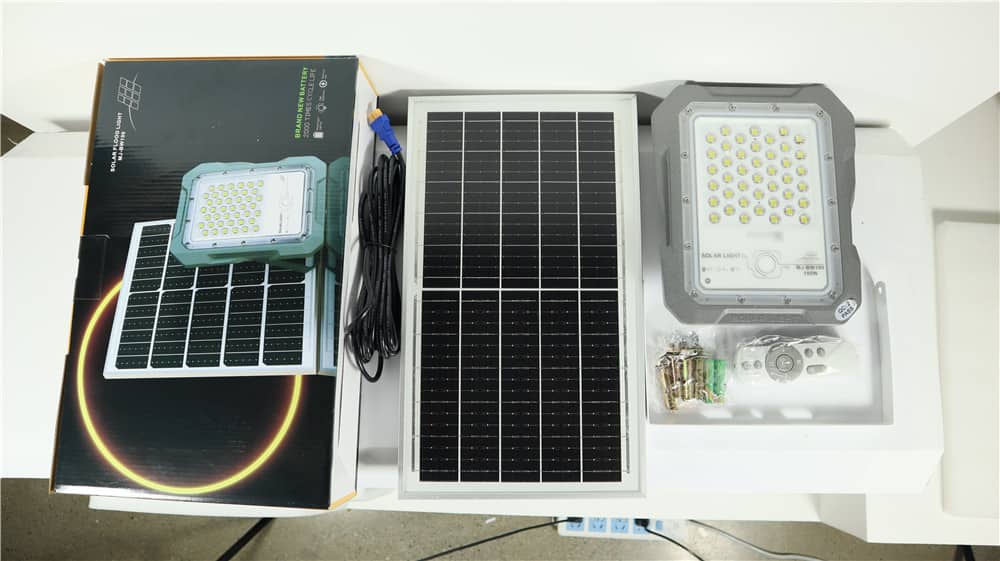
Identify the exact light and panel supplied, including the model version and any ordered options. Check the packing list against the brackets, cables, connectors, and accessories in the package. Where a product family offers different arrangements, a familiar appearance is not enough to establish that an earlier installation's instructions still apply.
Read the installation and first-use instructions before planning the final layout. Note the permitted mounting arrangements, bracket movement, cable limits, connector requirements, initial charging procedure, and any sensor-position restrictions. If information is missing, obtain it from the supplier before making a physical modification or choosing a fixing method that depends on it.
Record the target area's shape, important approach directions, nearby windows or roads, and likely obstacles. Then identify the actual mounting material and condition. A sound structural support and a thin decorative surface are not interchangeable. The responsible installer should select suitable fixings for the surface, load, and exposure instead of assuming that every supplied accessory suits every wall.
The MJ-AW solar flood light information can help identify that product family when requesting the appropriate installation documents. Confirm the supplied version and accessory list; a product page is not a substitute for the instructions and restrictions for the unit being installed.
Use Competent Personnel for Work at Height and Structural Fixings
Plan safe access for both installation and later maintenance. Roof edges, ladders, elevated walls, fragile surfaces, and structural fixings may require competent installers and appropriate access equipment. Assess these needs before deciding that the panel should go on the highest available surface.
Before fixing brackets, have the installer consider concealed services, the suitability of the building surface, and permission to use it. A standalone solar light avoids a mains connection at the fixture, but it does not remove risks from drilling or working at height. This guide supports layout and acceptance; the product instructions and qualified site assessment determine the physical installation method.
Choose the Light Position and Panel Position Separately
Position the Light to Meet the Lighting Task and Avoid Glare
Start by marking what needs to be seen: the entrance threshold, a section of driveway, an activity area, or a sign face. Also mark the normal viewing positions. A light that looks bright from directly below may still leave the intended target unevenly illuminated or place the LED source uncomfortably in someone's line of sight.
Consider obstructions between the light and its target. A canopy edge, open door, parked vehicle, or plant may cast a shadow where visibility is needed. Check the likely conditions during actual use, not only an empty daytime scene. For a sensor-equipped version, examine the detection area separately from the light beam and follow its mounting guidance.
Aim to keep useful light on the target and reduce spill toward neighboring windows, traffic, or unrelated areas. When a location is subject to specific lighting requirements, have the responsible designer verify them. A broad beam and a high wattage label do not establish an acceptable layout.
Position the Panel for Usable Sunlight Within the Approved Cable Reach
Survey the proposed panel location at different times and consider seasonal shade. A position under an eave may protect the lamp while depriving its panel of useful sunlight. A nearby open wall or roof position may improve exposure, provided its mounting conditions and approved connection route are suitable.
Measure the cable route along the surfaces it will actually follow. Include changes of direction, transitions between mounting surfaces, and any length needed for the manufacturer's connection and strain-relief arrangement. Straight-line distance between the light and panel can underestimate the required cable. Do not depend on pulling the lead tight to make it reach.
Choose the location and cable arrangement together. A sunny position outside the approved reach does not become suitable simply because an unverified extension can physically connect it. If the route is too long, revisit the positions or request an approved alternative configuration before installation.
How Should You Choose Mounting Height and Aiming Angle?
Consider Beam Distribution, the Target Area, and Maintenance Access
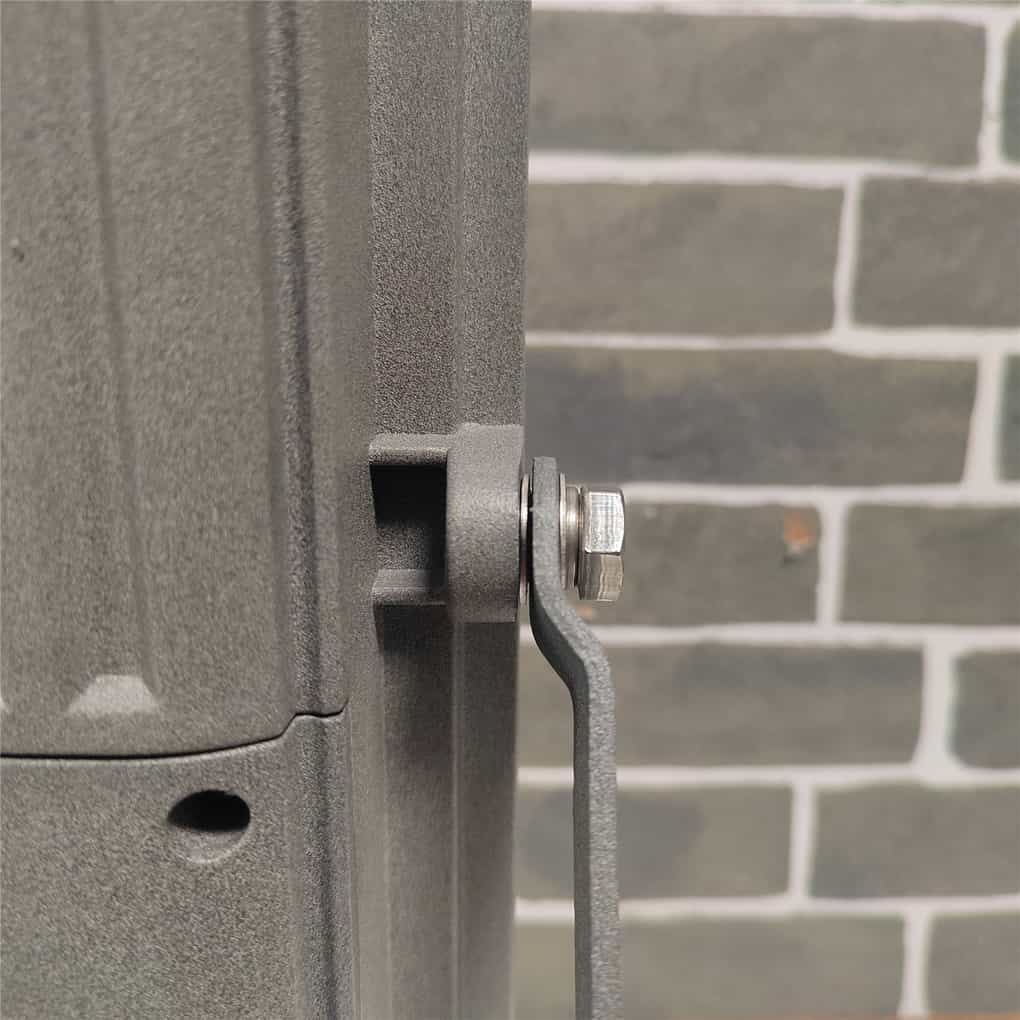
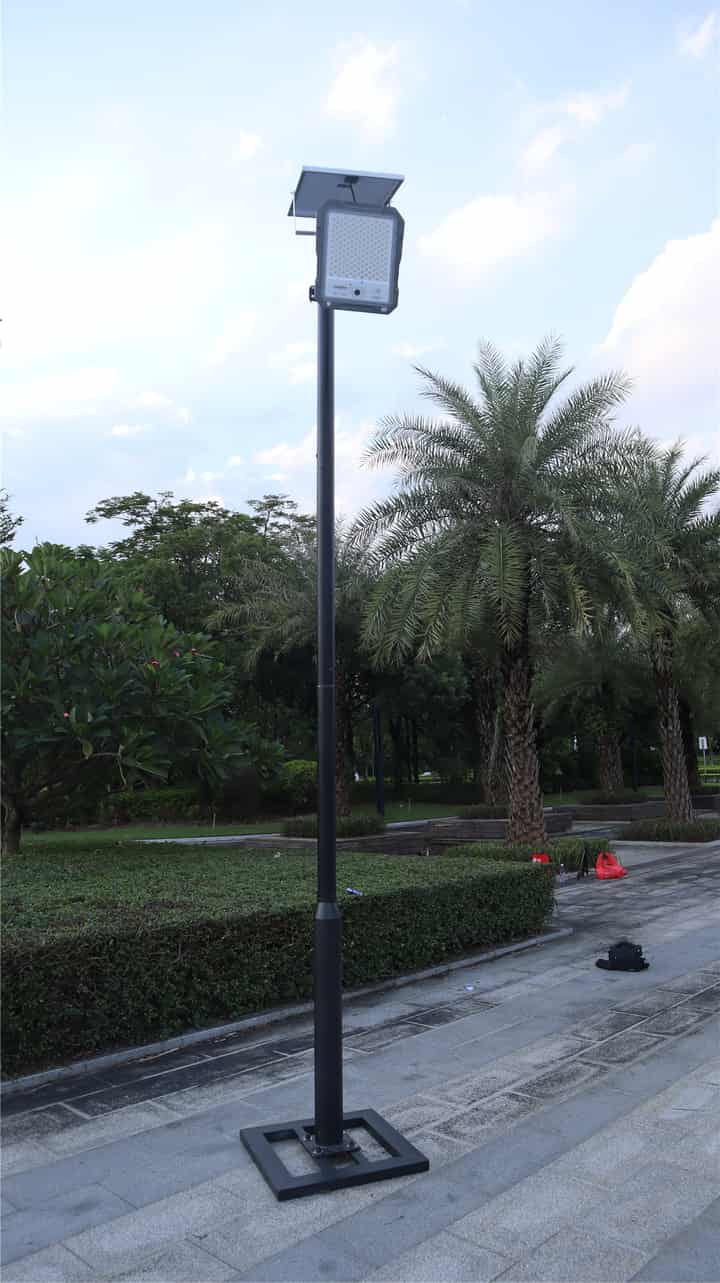
The best mounting height for solar flood lights depends on the beam distribution, required coverage, target surface, and aiming geometry. Raising a light changes how its output is distributed across the area; it does not automatically improve visibility. An apparently wider footprint can come with lower illumination at relevant points or more spill beyond the target.
Assess height and aiming as a pair. Pointing a fixture farther outward may reach a distant area while putting more light into approach views or neighboring spaces. Some sites need a different position, a different beam, or more than one appropriately selected fixture rather than a steeper tilt of the same unit. Ask for model-relevant lighting information when the layout cannot be judged confidently by a trial.
Maintenance access is part of the decision. The panel may need inspection and cleaning, and the light's settings or external connectors may need checking under the permitted procedure. A placement that is difficult to reach can make simple upkeep impractical. Confirm how service will be performed without making routine access depend on unsafe improvisation.
Test the Lighting Effect Before Final Positioning
Where practical, have the installer conduct a safely secured trial or use the product's approved adjustment range before accepting the final aim. Do not balance a loose fixture at height for testing. The trial should represent the intended mounting geometry and operating mode closely enough to answer the actual lighting question.
Observe from the entrance, target area, and relevant approach directions. Check both central and edge visibility, shadows around obstructions, and glare. A photograph can record the arrangement, but automatic camera exposure can conceal differences. Use consistent observation conditions and appropriate measurements when the project requires them.
Change one layout factor at a time and record the result. If aiming the light to reach one target creates unacceptable glare elsewhere, stop treating adjustment as an endless compromise. Reassess the position or product selection. Once the result is acceptable, record the final height and orientation for handover; those are site records, not universal recommendations for other installations.
Can You Extend the Cable, and What Must Be Checked?
Confirm Supplied Length, Maximum Approved Total Length, Wire Gauge, Polarity, and Connector Compatibility
Cable extension is a model-specific question. Ask the supplier to distinguish the length supplied, any approved additional lead, and the maximum approved total connection length. A listing that offers an extension accessory does not, by itself, define how many accessories may be combined or the resulting approved total length.
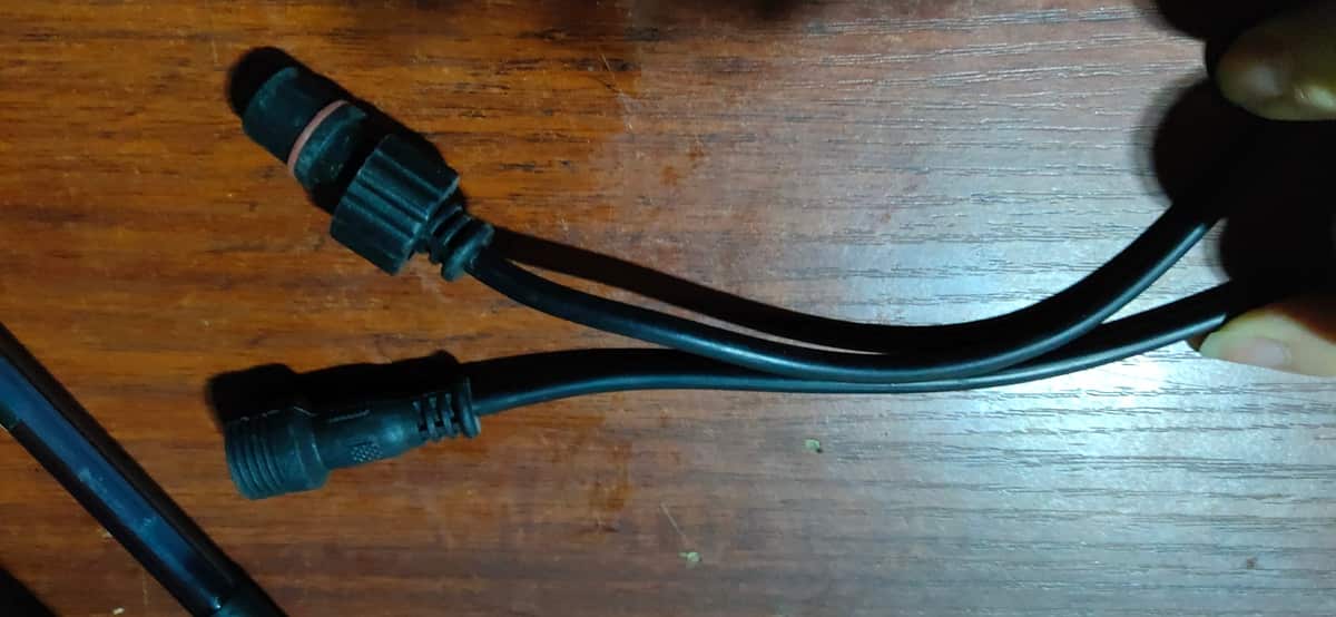
The cable must also have the required conductor specification, electrical compatibility, polarity arrangement, and connector type for the system. Appearance alone is insufficient. Added length can affect the electrical behavior of the connection, so an extension should be approved for the exact panel and light arrangement, not selected solely because it fits physically.
For a JD-family installation, the JD product identification page is a starting point for a model-specific inquiry. Send the complete intended route length and ask the supplier to confirm the permitted total and matching accessory. Do not convert a product-page accessory description into a general extension allowance.
The installer should verify compatibility from manufacturer information. This is not a reason for an owner to probe terminals, reverse connections experimentally, or adapt an unrelated cable. If the approved information is unavailable, keep the installation within the documented supplied arrangement or select a configuration with adequate verified reach.
Follow the Manufacturer's Requirements for Cable Routing and Connector Protection
Plan a route that avoids sharp edges, moving doors, pinch points, abrasion, and places where the cable could become a trip hazard. Use the support and protection method appropriate to the product and site, allowing the specified connection and strain-relief arrangement. Do not leave the weight of a hanging cable pulling on a connector.
A waterproof connector depends on the correct mating components and the required closure method. Follow the product instructions for sealing and positioning; a connector's label does not make an incomplete or contaminated joint reliable. Where the specified route or arrangement calls for avoiding water accumulation, preserve that detail in the finished installation.
Do not cut off connectors, improvise splices, or combine arbitrary extension leads to overcome a planning problem. A connection hidden behind tape is not evidence of the intended protection. Return to an approved accessory or revised layout, and leave internal electrical changes to the supplier's authorized service process.
Inspect the Mounting and Connections
Confirm Bracket and Surface Compatibility, Without Pinched or Strained Cables
Before accepting the installation, have the responsible installer confirm that each bracket and fixing suits its mounting surface and has been secured according to the relevant instructions. Check that the allowed adjustment has not been exceeded and that changing the lamp angle has not pulled the cable tight.
Inspect the complete visible cable route, including transitions around edges and brackets. Verify that no cable is trapped behind the mounting hardware or placed where routine door movement or maintenance will damage it. Record any portion that will become difficult to inspect later so the handover explains its route and access arrangements.
Check Connector Closure and the Final Panel and Light Angles
Under the manufacturer's permitted procedure, confirm that external connections are complete and closed as required. Do not force mismatched plugs or continue with damaged connector parts. A visibly damaged cable or connector needs supplier assessment before the system is put into service.
Recheck the panel position after tightening: the final angle should match the assessed exposure, with no new obstruction introduced by the completed installation. Recheck the lamp aim from real viewing positions as well. Photograph both positions and the route so future support does not have to reconstruct the arrangement from memory.
Complete Initial Charging and Nighttime Commissioning
Follow the Initial Setup Instructions and Check Modes and Detection Areas
Complete the exact model's first-use and charging procedure before judging runtime. Record the selected mode and any supported brightness, timer, or sensor settings. A lamp tested with an unintended timer or incomplete initial preparation can produce a misleading acceptance result.
Use the documented test procedure for daylight or sensor checks. Some lights will not turn on normally while daylight is detected, so a daytime non-response is not automatically an installation fault. Do not improvise a test that changes connections or bypasses controls. If the prescribed indication is unclear, ask support to explain it for the supplied version.
For a motion-equipped product, test relevant approaches and the behavior after activity stops. Check whether the actual detection area serves the site and whether surrounding movement creates unwanted activation. Record the observed pattern together with mounting position and mode, since all three affect the interpretation.
Record Coverage, Glare, Performance Over Time, and Maintenance Access
Nighttime acceptance should include the intended target and nearby areas affected by spill. Observe switch-on behavior, later-night output, and any programmed transitions that matter to the application. A brief bright demonstration cannot confirm a schedule extending for several hours or a full night.
Keep weather and sunlight observations with the record. Initial commissioning confirms installation and observed operation under those conditions; it does not automatically prove performance throughout the difficult season. Where seasonal service matters, agree on additional representative observation as part of the project acceptance plan.
Use the checklist below to divide responsibility and avoid leaving important checks until after access equipment has been removed.
| Stage | Check | Handover evidence |
|---|---|---|
| Before installation | Exact model, version, manual, accessory list | Product identification and matching document reference |
| Before installation | Target area, viewing directions, panel exposure | Marked photographs and site notes |
| Before installation | Actual cable route and approved total reach | Route measurement and supplier confirmation where required |
| During installation | Suitable surfaces, brackets, fixings, safe access | Installer's confirmation of the approved arrangement |
| During installation | Supported cable route and completed external connectors | Photographs showing accessible joints and routing |
| During installation | Final panel position and lamp aiming | Recorded positions and any approved adjustments |
| Nighttime acceptance | Coverage, shadows, glare, intended mode transitions | Observation record and measurements where required |
| Nighttime acceptance | Sensor response and later-night behavior | Settings record, observations, and relevant weather |
| Handover | Maintenance access, responsible person, support information | Maintenance plan and outstanding actions |
Close the installation with a clear record of the approved layout, settings, and any remaining observation period. If a check fails, identify the specific issue for the installer or supplier rather than accepting it because the lamp turns on. Successful commissioning means the installed arrangement has been checked against its intended service, with its observed conditions recorded.
At a rain-exposed or dusty site, include weather exposure and maintenance access in commissioning. Have the installer check the permitted orientation, completed connections, runoff or standing-water risks, and the suitability of exposed fixings. Record how the panel can be inspected and cleaned safely without stretching the cable or changing the approved arrangement. Do not conduct elevated inspections during a storm or assume that an IP label covers flood exposure, wind loading, and corrosion together.
Frequently Asked Questions
How Far Can the Panel Be Installed from the Light?
Use the approved total cable length for the exact supplied configuration, measured along the real route. Check whether a stated extension allowance means additional length or total length. If the required route exceeds the documented limit, request a compatible alternative configuration or revise the positions.
What Should I Check When Installing Solar Flood Lights in Areas with Heavy Rain?
Confirm the environmental suitability of the complete installed kit, including connectors and cable entries, not only the lamp enclosure. Use the approved mounting orientation and connection method, and have the installer assess runoff, standing water, and exposed fixings. A water-ingress rating does not make every location suitable for flooding or prove that a bracket meets the site's wind conditions.
Can I Use an Ordinary Extension Cable?
Do not assume it is suitable. A general cable or physically similar connector may have the wrong specification, polarity arrangement, or outdoor connection protection. Use an accessory approved for the exact system and total route, following the manufacturer's instructions without improvised splicing.
What Is the Best Mounting Height for Solar Flood Lights?
The best mounting height is the permitted position that delivers the required coverage without unacceptable glare and still allows safe maintenance. Use the exact fixture's distribution and mounting instructions, then test the intended area at night. A height suitable for one beam or driveway may be unsuitable for a different entrance, sign, or bracket arrangement.
Can the Solar Panel and Flood Light Face Different Directions?
A separate-panel model can allow different directions when its approved brackets, cable, and installation limits support the layout. Aim the light at the task and assess the panel for useful sunlight separately. Confirm the actual routed cable distance and access to both components before fixing them; independent aiming is not permission to extend or modify the system without approval.
How Should I Plan Solar Panel Cleaning Access at a Dusty Site?
Choose an approved mounting position that allows safe inspection and the manufacturer's cleaning method without creating new shade or exceeding cable limits. Base the inspection schedule on observed accumulation and operating changes rather than a universal interval. Arrange competent access where needed; do not rely on staff climbing improvised supports or using pressure cleaning unless the instructions explicitly permit it.