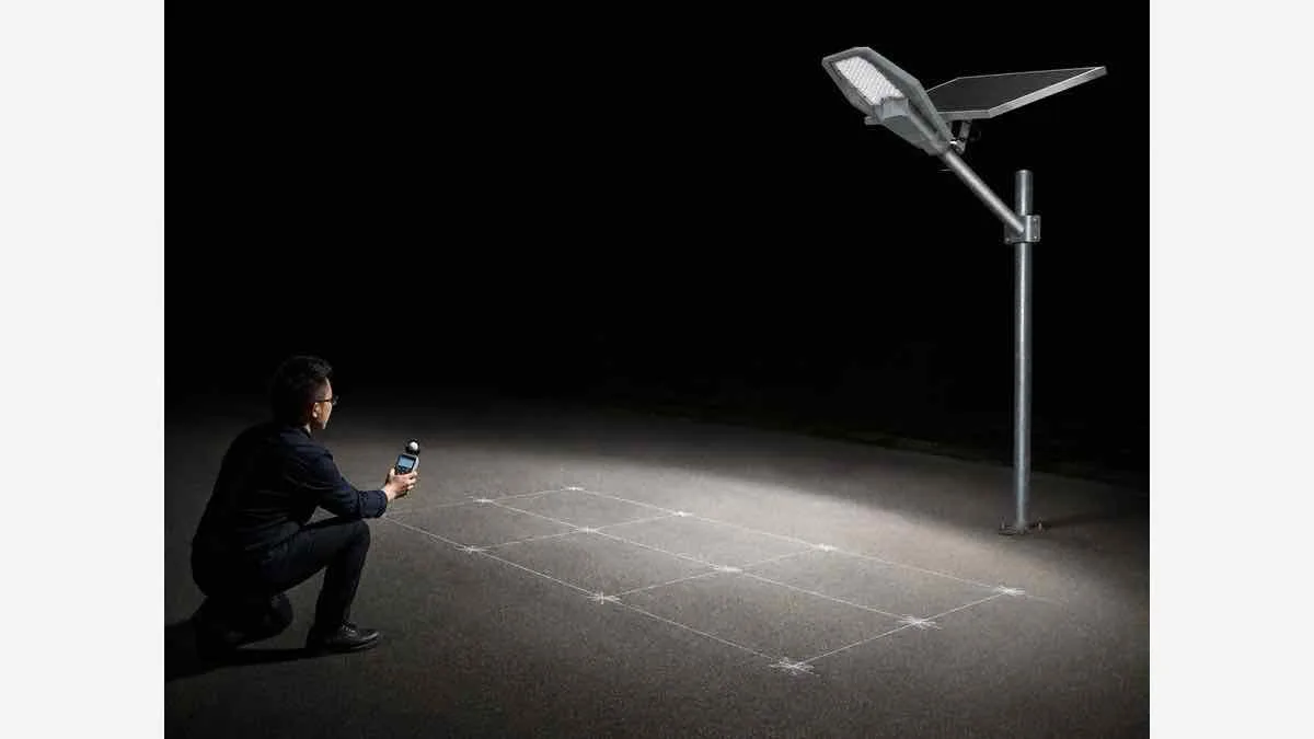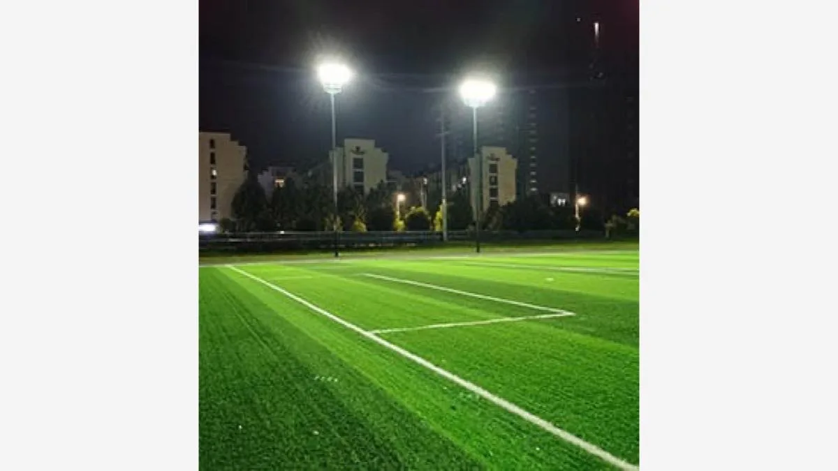


A correct solar street light installation must do more than hold a lamp on a pole. It must give the solar panel reliable access to sunlight, distribute light across the intended road area, resist local wind and soil conditions, protect every connection from water, and remain serviceable. Pole height, spacing, foundation size and panel angle therefore cannot be selected from wattage alone. Collect the site data first, verify the lighting layout, then install and commission the system as a complete energy-and-lighting package.
For an overview of available architectures, start with Newskypower’s solar street light range.
Solar Street Light Setup: Quick Installation Steps
Before installing solar street lights, use this sequence to organize the work. Keep the approved site drawings and the supplied model's manual together; each step below links to the relevant checks.
- Check the kit and site. Match components to the packing list and confirm pole positions against the site information.
- Accept the foundation. Check anchor alignment, cable access and the required concrete strength before releasing it for installation. See foundation preparation.
- Assemble at ground level. Fit the appropriate brackets and arrange the panel and lamp for their intended directions. Follow the assembly method for the system type.
- Connect and test before lifting. Follow the model's connection and activation sequence, check charging and basic operation, and resolve faults while accessible. Use the system testing checks.
- Erect and secure the pole. Follow the lifting plan, check vertical alignment and tighten specified fasteners. See pole erection and final assembly.
- Commission and hand over. Verify settings and nighttime coverage, then record results using the installation checklist.
Tools and Components to Prepare
| Task | Prepare and check |
|---|---|
| Measure and inspect | Tape measure, spirit level and an angle gauge; an appropriate meter only where the manual calls for electrical measurements at accessible test points. |
| Tighten fasteners | Matching spanners, sockets or hex keys; a torque wrench for specified torque values; the model's anti-theft tool where required. |
| Lift and access | Lifting and access equipment selected for the load, reach and ground conditions; barriers and protective equipment specified by the site plan. |
| Match the components | Pole, anchor hardware, brackets, fasteners and the correct light assembly. For separate-panel systems, check panel brackets and matching cables; for split systems, also check the separate battery/controller enclosures and mounting hardware. |
Check the supplied kit before arranging the installation crew. Resolve missing hardware or incompatible mounts before work begins.
Installation Compatibility and Supply Scope Before Ordering
A mounting illustration shows an arrangement, but does not establish compatibility with every existing pole. Use this table to turn the proposed solar street light installation into an itemized supply agreement. Record the matching model or drawing and identify who supplies each part.
| Item to resolve | Compatibility evidence | State in the quotation |
|---|---|---|
| Pole-top or arm interface | Measured outside diameter, usable insertion length and obstructions compared with the offered mount drawing. | Exact mount or adapter, fasteners and any required arm modification. |
| Light and panel orientation | Road-facing lamp position and available panel orientation, with seasonal shade considered. | Mounting arrangement and adjustment options for the selected model. |
| Existing pole and foundation | Condition and capacity review for the proposed equipment weight and wind area, including anchors and foundation. | Whether poles or foundation hardware are supplied; who handles assessment and civil work. |
| Operation and electrical connections | Required nightly profile matched to the proposed system; model-specific connector and controller instructions. | Controller configuration, separate cables or enclosures where applicable, and any programming responsibility. |
| Installation and handover | Mounting instructions, specified tightening requirements and agreed acceptance checks. | Manuals, agreed spare parts and responsibility for lifting, installation and commissioning. |
Treat anything absent from the quotation as unresolved. A price for the light does not by itself include a pole, anchor cage, lifting equipment, site installation or engineering design.
Information to Collect Before Installation
Record the project location, road width, lane and sidewalk arrangement, target lighting level, nightly schedule, proposed mounting height and quantity. Add local solar resource, seasonal weather, trees and buildings, soil and drainage, design wind conditions, underground utilities and access for lifting equipment. These inputs allow the lighting, electrical and structural teams to work from the same assumptions.
If the lamp has not yet been selected, complete a project-specific solar street light design calculation before fixing pole positions.
How to Plan Pole Height and Spacing
Why pole height affects coverage and illuminance
A higher mounting point can spread light over a larger area, but the illuminance reaching the pavement may fall unless the luminaire output and optics support that height. A lower pole concentrates light but may require more poles and can create brighter and darker zones.
Why spacing-to-height ratios are only a starting point
A spacing ratio cannot account for road width, lens distribution, setbacks, intersections, pedestrian conflict, surface reflectance or the required uniformity. Use preliminary ratios only to create a first layout, then verify it with the actual IES or LDT photometric file.
Single-side, staggered and opposite-side layouts
Single-side layouts suit some narrower roads. Staggered or opposite layouts may improve coverage on wider roads, but they change quantity, foundation positions and glare. FHWA guidance treats mounting height, pole spacing, photometrics, road geometry and required lighting quality as connected design variables.
When simulation is required
Use a DIALux or equivalent calculation when the road is wide, curved or multi-lane; when a tender defines illuminance or uniformity; or when glare, spill light, intersections or mixed pedestrian traffic matter. See the companion guide on commercial solar street lights for road projects.
How to Select the Installation Position
Inspect shade at several times of day. Trees, buildings, signs and utility lines can reduce charging even when the location looks clear at noon. Confirm that the luminaire faces the road while the panel keeps its required solar orientation. Keep the pole clear of drainage paths, vehicle swept paths, pedestrian access and unsafe roadside positions. Local authorities and qualified designers should approve final locations.
Solar Street Light Foundation Preparation
Foundation design inputs
Foundation design depends on pole height and geometry, luminaire and panel wind area, local design wind speed, soil bearing and drainage conditions, anchor arrangement and local structural requirements. There is no responsible universal foundation depth. Obtain an engineered drawing when project risk or local rules require it.
Anchor cage, conduit and concrete preparation
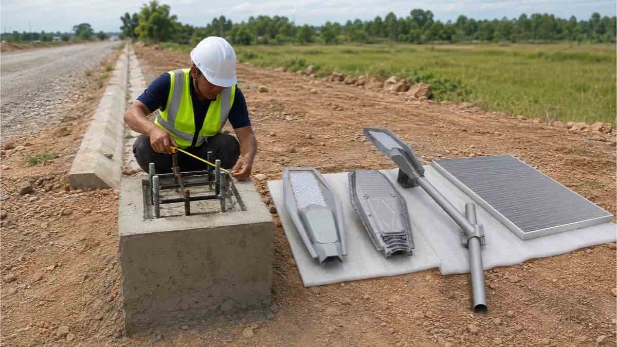
Set the anchor cage to the specified orientation and elevation. Protect threads, keep the template level, and route conduit so cables are not sharply bent or exposed to standing water. Confirm reinforcement and concrete requirements against the approved drawing.
Curing and alignment checks
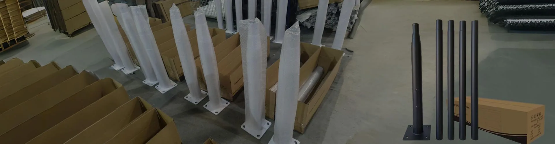
Do not erect the pole until the concrete has reached the strength required by the project engineer. Recheck bolt spacing, projection, level, drainage and cable access before lifting. The light pole manufacturer page provides context for coordinating poles with the luminaire system.
How to Assemble Different Solar Street Light Types
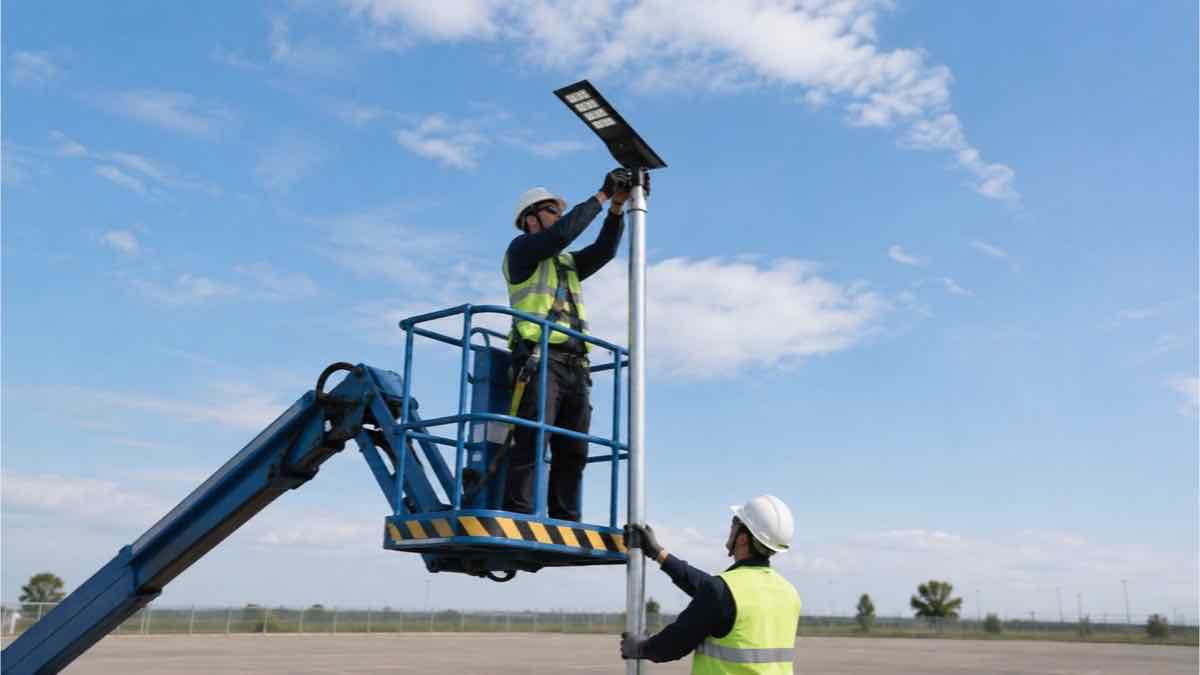
All-in-one solar street light installation
An all-in-one solar street light normally reduces field wiring because the panel, battery, controller and LED are integrated. Confirm arm diameter, tilt options, orientation, activation procedure and fastener torque before lifting.
LKX Mounting Example: Pole Top or Horizontal Arm
For an integrated solar street light installation, check how the supplied mounting socket fits the pole before lifting. The LKX manual illustrates two arrangements: fitting onto a vertical pole top and fitting over a horizontal arm.
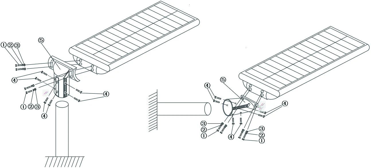
LKX mounting arrangements from the model's user manual.
Match the chosen arrangement to the supplied mount and approved lighting direction. The LKX manual identifies M8 × 20 hexagon socket bolts and instructs the installer to tighten the anti-theft screws with a special tool, then confirm that the light is stable. This fastener specification applies to LKX; confirm the supplied hardware rather than transferring it to another model.
The manual also specifies activation through the waterproof switch, daytime charging and automatic nighttime operation. Follow the supplied manual’s initial-charge instructions before routine nighttime use. Include these functions in the ground-level check before final lifting and commissioning.

All-in-two solar street light installation
An all-in-two design normally separates the panel from the combined lamp and battery section. It adds mounting and cabling work but provides more freedom to aim the panel. Label mating connectors and protect cable loops.
NF Series Solar Street Light Assembly Example
The NF diagram shows how the panel bracket, rotating adapter, lamp body and pole mount fit together. Use the five-step sequence from the manual below; the diagram labels identify component connections.
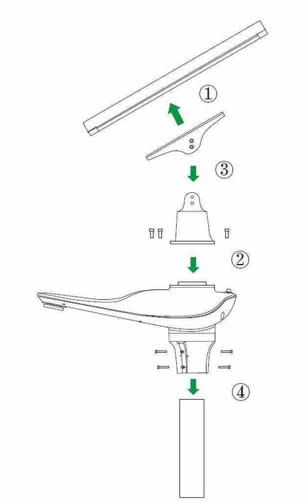
NF component arrangement. Check the panel-to-lamp cable separately before mounting the complete unit.
- Fix the bracket to the solar panel.
- Fix the rotating adapter to the lamp body.
- Set the required installation angle and secure the panel bracket to the adapter.
- Connect the panel to the lamp head with the cable and verify operation.
- Fix the complete unit to the pole.
For this NF configuration, the manual specifies 76 mm as the optimal pole diameter. Before installation, confirm that the supplied pole top and mounting adapter match. Do not use this diameter as a specification for other solar street light models.
Split solar street light installation
A split solar street light has separate panel, luminaire and battery/control components. It offers configuration and service flexibility but requires the most careful cable routing, polarity checks and enclosure placement.
Worked Example: Reusing Existing Poles with an LKX Candidate
Hypothetical planning example: an owner wants solar lighting along an access road with existing horizontal-arm poles at fixed positions. The owner has overview photographs, but no dimensioned arm drawing or current pole and foundation capacity records. The aim is to decide whether those poles can be retained.
LKX is an initial candidate because its manual shows horizontal-arm mounting. The next useful evidence is a measured arm outside diameter, usable insertion length and close-up photographs. Compare these with the drawing for the actual offered LKX mount. If they do not match, specify an approved replacement arm or adapter before ordering; the illustration alone is not a fit confirmation.
The fixed pole positions create a second decision. Check the proposed optic at those heights and spacings using its photometric file. If coverage cannot meet the project criteria, revise the optic or layout; simply choosing a higher advertised wattage does not resolve the layout. If road-facing orientation leaves the integrated panel shaded or poorly oriented, compare a separately aimed panel arrangement, such as NF, and reassess its mounting and wind load.
Under these assumptions, request a conditional LKX quotation, with the selected mount, specified fasteners, manual and agreed spare parts identified. Keep pole replacement, civil work and site services as separately defined scope. The missing structural records mean that retaining the poles remains subject to an engineer's assessment of the poles, anchors and foundations for the proposed assembly.
Once the design and interfaces are accepted, check one supplied assembly on the ground against the agreed configuration, including mounting fit, activation and the manual's initial-charge requirements. Nighttime handover must then compare the installed coverage and operating settings with the agreed acceptance criteria. A light that switches on but leaves unacceptable dark areas requires investigation of aiming, optics or layout before acceptance.
The decision is therefore to develop the LKX option while withholding installation approval until compatibility, lighting and structural checks support it.
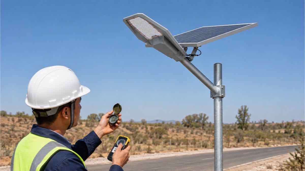
Solar Panel Direction and Tilt Angle
In the Northern Hemisphere, an unshaded fixed panel commonly faces generally south; in the Southern Hemisphere, it commonly faces generally north. The final azimuth and tilt should reflect latitude, seasonal solar access, terrain, local weather data and the months with the lowest useful resource. Avoid self-shading from the pole or luminaire. A generic angle copied from another country may reduce winter charging.
Pole Erection, Wiring and Final Assembly
Inspect components on the ground first. Check model numbers, damage, connectors, polarity labels, brackets and torque requirements. Use a qualified lifting plan, maintain exclusion zones, align the pole vertically and tighten structural fasteners to the approved specification. Weatherproof connectors must be fully seated, strain-relieved and positioned to avoid trapped water. Activate the battery and controller only in the manufacturer’s sequence. For transport-constrained sites, review modular light-pole options.

Testing and Commissioning the System
Confirm charging voltage/current or controller status in daylight. Cover or simulate the light sensor only by the approved method to test night mode. Verify the hourly dimming program, motion response and low-power behavior. After dark, inspect aiming, dark areas, glare and unintended spill; take measurements if the project has photometric acceptance criteria. Record pole ID, settings, date, readings, photographs and any corrective work.
Commissioning should also confirm that the installed equipment matches the approved schedule. Check luminaire model, optic, panel and battery identification, controller program and mounting height against the submittal. A light can switch on correctly and still fail the project if the wrong lens, program or mounting position was installed. For a multi-pole project, inspect a representative group across different road conditions rather than accepting only the easiest location.
Create a punch list for misalignment, damaged coatings, loose access covers, unexpected shade, water pathways and inconsistent settings. Close each item with a photograph or measurement. This record gives the owner a baseline for later troubleshooting and prevents installation defects from being mistaken for product aging.
Common Installation Mistakes
- Installing where seasonal shade reaches the panel
- Selecting spacing from advertised wattage alone
- Reusing a foundation detail without checking wind and soil
- Leaving connectors unsupported or exposed to water
- Connecting batteries with unchecked polarity
- Lifting before ground-level functional testing
- Skipping nighttime inspection and handover records
Solar Street Light Installation Checklist
| Stage | Check |
|---|---|
| Before work | Approved layout, utilities located, foundation/pole drawings confirmed, components matched |
| Foundation | Anchor cage level, conduit protected, drainage considered, curing accepted |
| Assembly | Panel orientation, polarity, cable protection and specified fastener torque verified |
| Commissioning | Charging, dusk switching, dimming, sensor response and nighttime coverage checked |
| Handover | Pole IDs, settings, photos, measurements, manuals and spare-parts list recorded |
Frequently Asked Questions
How high should a solar street light pole be?
Choose height from road geometry, optics, target lighting quality, spacing and structural constraints—not from wattage alone.
How far apart should solar street lights be?
Create a preliminary layout, then verify spacing with the actual photometric file and required uniformity.
How deep should the foundation be?
Depth and geometry depend on pole loads, wind, soil, drainage and local structural rules. Use an approved project drawing.
Which direction should the solar panel face?
Aim it toward the equator as a general starting principle, then optimize for local seasonal solar access and shading.
Can an all-in-one light use an existing pole?
Only after checking arm compatibility, structural capacity, wind area, orientation, cable/service access and owner approval.
How should the system be tested?
Test charging and functions on the ground, verify controller modes after erection, then inspect or measure the result at night.
Request a Preliminary Installation Review
Provide the project location, road width, proposed pole height and spacing, quantity, nightly operating hours, drawings and site photographs. Newskypower can use those inputs to discuss a preliminary system and layout; final lighting and structural approval remains project-specific.
Project Installation Enquiries
Planning an installation or checking an existing pole? Send the site location, road or pathway width, proposed pole height and spacing, quantity, nighttime operating schedule, and the components you expect us to supply through the Newskypower contact form. For a mounting check, include clear photos, dimensions or drawings of the pole-top or arm interface. You can also email inquiry@newskypower.com. We will review the requested mounting arrangement and supply scope before recommending a model; final lighting and structural approval remains project-specific.
More Solar Street Light Project Guides
Continue with the checks that most often affect an installation decision: light output, road layout, and the pole interface.